Measuring a dev board for 3D printing when the size is not published
If you just want a holder, do not read this. Search Printables, MakerWorld, Cults3D or Yeggi for your board and you will find a ready-made model, free, from people who have printed theirs. They have more models than this site will ever have and that is the right place to get one.
This page is about the step before a model exists: how you decide a dimension nobody has written down, and how you check a generated solid before you spend filament on it.
Nothing described here has been printed. The two parts this page refers to have not been printed — not by me, not by anyone I know of. Every check below is a check a computer performed on geometry. No printer, no caliper, no fit, no tolerance, no material result, no photograph of a part. Read this as a method, and judge the method; there is no finished object at the end of it.
What I tried, and what actually came back
The part in question parks an ESP32-S3-DevKitC-1. To cut a bay for it you need the board's outline width. The repository's own notes claimed that dimension could not be sourced: that the vendor's board page renders with JavaScript and that the dimensions PDF it links to returns 404. Before repeating a claim like that in public I re-ran it. The claim was stale, and this page is the correction.
What I got, this run. The documentation URL the notes were built on,
docs.espressif.com/projects/esp-dev-kits/en/latest/esp32s3/esp32-s3-devkitc-1/user_guide.html,
still returns HTTP 404 — so the original negative result reproduces exactly.
But one negative on one URL is not a proof of absence, and walking up the path shows why: the
directory index at .../esp32-s3-devkitc-1/index.html returns 200,
and every link in it points at user_guide_v1.1.html, which also returns
200.
The guide was renamed to a versioned filename, and the old unversioned path was simply left to 404. Nothing was withdrawn. A link rotted.
That guide's related-documents list includes an item labelled “ESP32-S3-DevKitC-1
Dimensions source file (DXF)”, served from
dl.espressif.com/dl/schematics/esp_idf/. It returns 200, as
image/vnd.dxf, 743,753 bytes, alongside a PDF rendering of the same drawing at
124,348 bytes. The dimensions source exists and is public. Publishing
“you cannot get this” when you can is the same category of error as inventing a
number, so the bench parts page now carries the
correction.
One place still carries the old wording, and it is worth saying which. The
original claim is a header comment inside
models.cjs, and that
file's body is concatenated verbatim into the geometry module the browser runs — the
string “JS-rendered” is present in the committed module today.
The parity check described at the end of this page asserts that module byte for byte, so rewriting one sentence of English in the generator is not a prose edit; it forces a regeneration of the geometry and a re-verification of the plate against the published STL.
That is a different
change from writing this page, and doing it as a drive-by is exactly the habit the check
exists to prevent. So models.cjs.txt still reads “its linked dimensions PDF
404s”. It is wrong, this page is the current reading, and the correction is owed to the
generator the next time its geometry is legitimately rebuilt.
Available is not the same as written down
So I opened the DXF. It is an AutoCAD 2013 file, and it contains zero DIMENSION
entities — there is not a single dimension callout in it. Its text entities are
silkscreen designators: R9, U4, J2,
ESP32-S3-DevKitC-1.
The header's drawing extents cover the whole annotated sheet rather than the board outline, so reading them as a board size would be wrong by a wide margin. The PDF rendering has no extractable text layer at all; it is a picture of a drawing.
This is the useful lesson, and it is more general than one board. The authoritative source is vector geometry, not a table of numbers. To get a width out of it you open it in CAD and measure the outline yourself.
So measuring is not avoidable here — it was never avoidable. The only real choice is where you measure: in CAD, against a file, or in plastic, against the board on your desk. Both are measurements. Neither is a number someone handed you, and that is exactly why this page will not quote one.
Why a printed gauge beats a confident guess
The measurement instrument here is a stepped gauge: six U-channels of increasing width,
24.6, 25.0, 25.4, 25.8, 26.2 and 26.6 mm, defined in
models.cjs. You lower
the board into each from above; the narrowest channel it settles into without forcing is the
board width, to within the 0.4 mm step.
A rib count beside each channel identifies it, so the reading survives putting the part down and picking it up again. The channels are only 16 mm long and open at both ends, so you engage a short section of the PCB edge instead of fighting the pin headers.
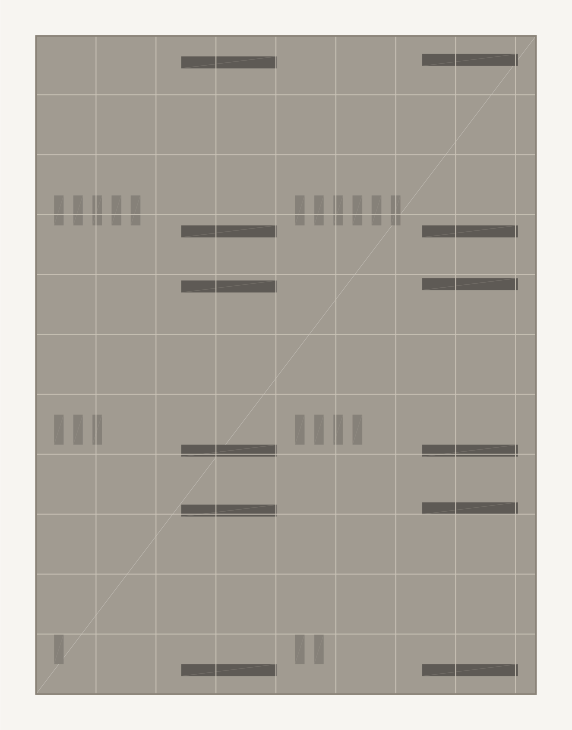
esp32-fit-gauge.stl's own bytes by
verify-stl.cjs
— a render, not a photograph of a part. The step between neighbouring channels is
finer than this drawing resolves at page size, so identify a channel by counting the ribs
beside it rather than by eye off the picture; the STL itself and an isometric view of the
same mesh are on the ESP32-S3 bench parts
page.Those six numbers are the band published as an STL here, chosen to straddle the board this site is measuring — which is no use to you if you are holding something else.
The ladder
is not welded to them: fitGauge() takes an optional centre, so
re-running the generator with a rough estimate of the width you are after emits the same six
channels at the same 0.4 mm step, re-centred to straddle your estimate — three
channels below it, three above, and none landing exactly on it, so every channel gives a
verdict rather than a shrug.
A ladder of six trial widths is cheap. A guess is not, because a guess is indistinguishable from a fact once it is written into a parameter file — and search will happily hand you a confident width belonging to a different board in the same family. The gauge cannot be wrong in that way. It has no opinion; it only fails to fit.
Make being wrong cheap: leave the uncertain axis open
The second half of the method costs nothing and matters more. In the bench plate, the devkit bay is open at both ends on purpose. Only the width is constrained; the length is not. Get the length wrong and the board simply overhangs the end of the bay. It cannot fail to fit.
That is a design decision made specifically because a dimension was uncertain: you spend a constraint only on the axis you can defend, and you let the axis you cannot defend run off the edge of the part.
test-fit.cjs
asserts that openness rather than trusting it, with a check whose name says what it is for:
“the devkit bay is OPEN end to end, so an unverified board LENGTH cannot bind”.
Four layers between the geometry and the printer
Generated geometry looks right in a preview long after it has stopped being right. Four independent checks stand between the model and a print, and one of them caught a real defect.
- The mesh cannot self-overlap.
stl.cjsbuilds solids as boxes that touch but never interpenetrate, and itscheck()rejects any pair with positive overlap on all three axes at once — the self-intersecting shells that make slicers produce nonsense. - The dimensions are asserted, not eyeballed.
test-fit.cjstakes a scan line through the finished solid at wall height and reports the clear span, the way a caliper would. Running it now returns26 assertion(s) passed. This is the layer that earned its place: during design it caught a stray term that had inflated the devkit bay by millimetres, which would have left the board rattling in a part that still looked correct on screen. - The bytes on disk are re-read by a stranger.
verify-stl.cjsparses the written STL again with an independent reader, because a generator validating its own memory tells you nothing about what landed in the file. The same pass also counts, for every edge it parsed, how many triangles use that same line, and prints the tally: the plate comes back as140 undirected edges, 0 used once (an open shell), 4 used more than twice. Those four are the vertical corners where two wall boxes stand against each other; the writer has no boolean union, so the plate is several touching skins rather than one closed surface. That is how the part is built, not a defect that crept in, and the tool reports the number for every file it reads without ever asserting it. Nothing is written at all unless the mesh check passes first — seebuild.cjs, which leaves no file behind when a model is invalid. - The copy in your browser cannot drift from the copy on the command line.
This is the strongest layer. The same geometry now runs client-side from
geometry.js, andtest/web-geometry-parity.test.cjsfails if that served module differs by one byte from the CLI source, or if the solids it builds stop matching the published STLs. Its output, verbatim, from this run — one line, wrapped here to fit:
ok web-geometry-parity — geometry.js is a byte-exact render of stl.cjs + models.cjs;
the plate it builds is byte-identical to models/esp32/esp32-bench-plate.stl
(4884 bytes, 96 triangles, 120.3 x 63.1 x 5.6 mm) and the comb to
models/esp32/jumper-wire-comb.stl (19884 bytes, 396 triangles, 84.01 x 9.08 x 5.6 mm)
Every number this page states, in one place. The table collects them and adds nothing: each value is repeated from the prose above in the unit the prose uses, and the last column says what, if anything, re-measures it.
Two rows have no value, and those two are the most useful rows in the table — a missing number is the thing this page is about, so they are marked and explained rather than filled in with something plausible.
| Dimension | Value | Unit | Where the number came from, and what it is asserted against |
|---|---|---|---|
| ESP32-S3-DevKitC-1 outline width | no value | mm | Left empty on purpose. Nothing on this page states it. The DXF carries zero DIMENSION entities and the PDF rendering has no text layer, so there is no number to copy across; writing a plausible one here would be the exact failure the page argues against. This is the cell the gauge exists to fill, on your desk, for your board. |
| Devkit bay length, bench plate | no value | none | Left empty on purpose. There is no length to state: the bay is open
at both ends, so a board longer than the bay overhangs instead of binding.
test-fit.cjs
asserts that openness directly. |
| Fit-gauge channel widths, six channels | 24.6, 25.0, 25.4, 25.8, 26.2, 26.6 | mm | Literals in models.cjs,
published as esp32-fit-gauge.stl. Chosen to straddle the board this site is
measuring; fitGauge() re-centres the same ladder on an estimate you supply. |
| Step between neighbouring channels | 0.4 | mm | The spacing designed into that ladder. It is the resolution of a reading, not an accuracy claim: the gauge tells you which channel the board settles into, no finer. |
| Fit-gauge channel length | 16 | mm | models.cjs.
Short, and open at both ends, so the board engages a section of PCB edge rather than the
pin headers. |
esp32-bench-plate.stl, bounding box |
120.3 x 63.1 x 5.6 | mm | Quoted from the parity line above, which measures the written file's own bytes with an independent reader instead of trusting the generator's memory. |
jumper-wire-comb.stl, bounding box |
84.01 x 9.08 x 5.6 | mm | Same line, same run, same independent reader. |
esp32-bench-plate.stl, mesh size |
96 | triangles | Counted out of the file by the same pass. Reported, not asserted against a hand-written figure. |
jumper-wire-comb.stl, mesh size |
396 | triangles | Same pass, same run. |
| Bench-plate edges used by more than two triangles | 4 | edges | Out of 140 undirected edges, 0 used once, as
verify-stl.cjs
prints it. Reported and never asserted: those are the vertical corners where two wall
boxes stand against each other, because the writer has no boolean union. |
| Dimensional assertions run against the finished solids | 26 | assertions | test-fit.cjs
on this run: 26 assertion(s) passed. It scans the solid at wall height and
reports the clear span, the way a caliper would. |
What you may do with the code this page hands you. Separately from whether
the method is any good, you are free to use it. The generator and checking code linked
throughout this page — build.cjs,
models.cjs,
stl.cjs,
test-fit.cjs,
verify-stl.cjs and
the geometry.js the
browser runs — is MIT.
So: paste any of it into your own repository, swap the numbers for the board you measured, keep it private or sell what you build on it, without asking. What MIT asks in return is only that the copyright line and the permission notice travel with the copy you pass on; LICENSE-MIT.txt is plain text, opens in the tab, and is short enough to paste whole.
The geometry those scripts emit is a separate question with a separate answer: the STL and SVG files on the parts page are CC BY 4.0, and LICENSE-CC-BY-4.0.txt carries an attribution line you can paste as it stands. Permission is not a promise the code is right, and it is not a promise anything here fits: the notice at the top of this page still stands.
What this does not tell you
It does not tell you the board's width — the whole point is that you measure it. It does not tell you that any of this fits, because nothing has been printed. It reports no tolerance, no print time observed on a printer, no material result, and no experience from anyone who has used any of it.
What it offers is a way to proceed honestly when a number you need is missing: check whether it is really missing or just moved, measure rather than assert, leave the uncertain axis unconstrained, and make the machine re-check the file it just wrote.
The parts and downloads this method produced are on the ESP32-S3 bench parts page, along with every source file quoted above.